Structural Assessments
AS Mosley has experience in determining structural capacities for a range of equipment from simple flow diverter C-Plates to wellheads and valve bodies requiring non-linear material models and contact relationships.
Important considerations for structural assessments and analysis are:
-
-
-
- Geometry/symmetry
- Boundary Conditions
- Contact
- Mesh validation
- Material model
- Loading
- Failure Criteria
-
-
Determination of accurate wellhead capacities through 3D FEA can give significant benefits in terms of extending well operating envelopes, especially when operations are required on older wellheads without rigid lockdown and little documentation on capacity.
Wellhead
A detailed half model of the wellhead is built including the conductor with P-Y soil springs and surface casing. Small radii and other structurally insignificant details are removed to improve meshing and model efficiency.
Elastic-plastic material properties are used with the model subjected to increasing axial compression, bending load, and combined compression and bending loading. Structural capacities are determined based on plastic strain limits outlined in ISO 13628-7.

Figure 1: Wellhead model

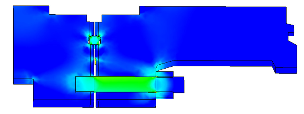
Figure 2: Wellhead under bending
Flow Diverter C-Plate
Load carrying C-plate thickness can be optimised as well as determining the minimum slip bowl diameter to ensure required working load limits can be achieved in accordance with an appropriate design safety factor from API codes for lifting equipment.
A half-symmetry model is used with linear elastic material properties and ensuring accurate modelling of frictional contact between the C-plate and flow diverter. The allowable stress limits are based on minimum material yield strength (Sy) using ASME methodology for linear materials. Structural capacity is acceptable if section stresses fall within the envelope shown in Figure 3 (including safety factor).

Figure 3- General primary section yield stress limits

Figure 4- Flow Diverter and C-Plate
For more information on Structural Assessments, please contact us directly.